Serial Operations for IEC
See also: IEC 61131 Language Editor Programming
See also: Project Toolbox for IEC
Topic Menu
Home > View > Project Toolbox > Serial Operations
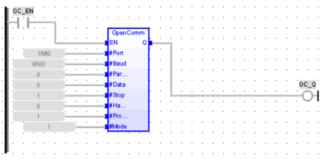
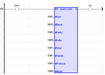
Open Communication Port
Operator - Performs the opening of a desired port for communication.
Inputs
EN : Enable input (TYPE : BOOL)
#Port: Port number (TYPE : DINT)
#Baud: Baud setting (TYPE : DINT)
#Parity: Parity setting (TYPE : DINT)
#Data: Data bits (TYPE : DINT)
#Stop: Stop bits (TYPE : DINT)
#Protocol: Protocol setting (TYPE : DINT)
#Mode: Mode of communication (TYPE : DINT)
NOTE: The above inputs can also be configured through registers. To do the same, please use "OpenCommReg" block. Refer to Open Comm Flexible Port for more details.
Outputs
Q : Output if the port open is successful (TYPE : BOOL)
Remarks
The Open Port element creates a channel to the desired communication port. The operational parameters (baud rate, etc) are also set by this element. The channel remains open until closed by the Close Port element or the controller is taken out of RUN mode. Refer to Operands for Communication Ports
ST Language
Q := OpenComm (EN, #Port, #Baud, #Parity, #Data, #Stop, #Handshake, #Protocol, #Mode);
FBD Language
LD Language
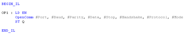
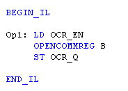
IL Language
Return to the Top: Serial Operations for IEC
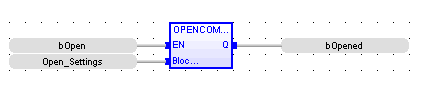
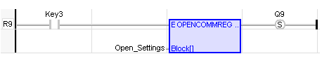
Open Comm Flexible Port
Also called: OPENCOMMREG See also: Open Communication Port
Inputs
EN: Enable.
BLOCK: An array of 8 UINT![]() Unsigned Integer - [Data Type UINT] - A 16-bit unsigned value. Unsigned Integers are used where the value of the data is expected to be in the range of -0 (zero) to 65,535.s specifying the parameters to be used to open the port.
Unsigned Integer - [Data Type UINT] - A 16-bit unsigned value. Unsigned Integers are used where the value of the data is expected to be in the range of -0 (zero) to 65,535.s specifying the parameters to be used to open the port.
Outputs
Q : TRUE if the port is opened, FALSE otherwise (possible parameter error).
This block opens a communication port with settings configured in an array of data. The settings are obtained from the Block as follows:
BLOCK[0]: Port number
BLOCK[1] Baud setting
BLOCK[2] Parity setting
BLOCK[3]: Data bits
BLOCK[4]: Stop bits
BLOCK[5]: Handshake
BLOCK[6]: Protocol setting
BLOCK[7]: Mode of communication
ST Language
bOpened := OPENCOMMREG (bOpen, OpenSettings);
FBD Language
LD Language
IL Language
Return to the Top: Serial Operations for IEC
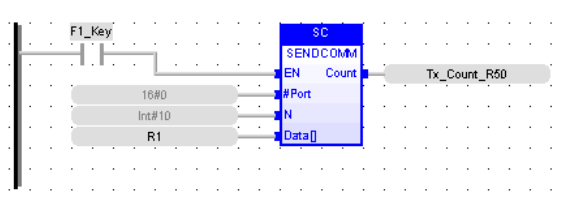
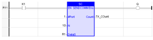
Send Data 
Operator - Performs transmitting of data through a opened port.
Inputs
EN: Enable input (TYPE : BOOL)
#PORT: Port number (TYPE : DINT) - This is comm port previously open by the ladder program.
N: (TYPE : INT) - This value indicates the number of bytes to be transmitted, may be specified as either a register reference or as a decimal constant.
DATA[ ]: (TYPE : USINT[]) - This is the address of the buffer containing the data to be sent. This must be specified as a Register Type and Offset reference.
Outputs
COUNT: (TYPE : INT) - The actual number of bytes transferred to the port's internal buffer (or -1 when the function is not active). This location must be specified as a register Type and Offset reference.
Remarks
-
If the port has been successfully opened, this element sends a specified number of bytes to the internal transmit buffer for the selected communication port. When power is applied to the element, the Output COUNT register contains the number of characters actually transferred to the comm port transmit buffer. If power is not applied to the element, this register contains -1 (negative one).
-
Power flow through the element is FALSE until the requested number of characters have been transferred to the comm port transmit buffer (at which time the power flow is TRUE). It is possible that the element can not transfer all data in one program scan time
 Time required for the controller to read its inputs, solve the Ladder Logic program, and write its outputs. Scan times are usually expressed in milliseconds.
NOTE: Scan times can vary, depending on number and complexity of Ladder Logic rungs that are active during the "solve" portion of the scan..
Time required for the controller to read its inputs, solve the Ladder Logic program, and write its outputs. Scan times are usually expressed in milliseconds.
NOTE: Scan times can vary, depending on number and complexity of Ladder Logic rungs that are active during the "solve" portion of the scan.. -
If the port is not open, the Transmit Element does nothing, and power flow through the element is FALSE.
-
If the value contained in BYTES is greater then 255, the element does nothing and power flow through the element is FALSE.
-
The Number of Bytes can be either a register references or a decimal constant. The maximum acceptable value is 255 bytes. When using a Register Type if it contains a value less than 0 (zero) or greater than 255, the element does nothing, and power flow through the element is FALSE.
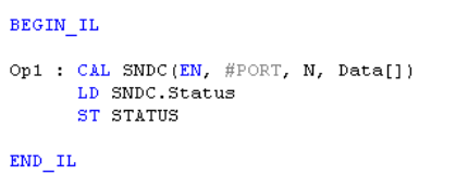
ST Language
(* SNDC is a declared instance of SendComm function block *)
SNDC (EN, #PORT, N, Data[]);
Count := SNDC.count;
FBD Language
LD Language
IL Language
(* SNDC is a declared instance of SendComm function block *)
Return to the Top: Serial Operations for IEC
Receive Data 
Operator - Performs receiving of data through an opened port.
Inputs
EN : Enable input (TYPE : BOOL![]() Boolean- [Data Type BOOL] - A single bit, binary value, or register/variable. Boolean points have only two possible values, 'TRUE' or 'FALSE'.)
Boolean- [Data Type BOOL] - A single bit, binary value, or register/variable. Boolean points have only two possible values, 'TRUE' or 'FALSE'.)
#PORT: Port number (TYPE : DINT![]() Double Integer - [Data Type DINT] - A 32-bit signed value. Double Integers are used where the value of the data is expected to be in the range of -2,147,483,648 to +2,147,483,647.) - Port number is the comm port previously open by the ladder program.
Double Integer - [Data Type DINT] - A 32-bit signed value. Double Integers are used where the value of the data is expected to be in the range of -2,147,483,648 to +2,147,483,647.) - Port number is the comm port previously open by the ladder program.
N : (TYPE : INT![]() Integer - [Data Type INT] - A 16-bit signed value. Integers are used where the value of the data is expected to be in the range of -32,768 to +32,767.) - This value indicates the number of bytes to be received.
Integer - [Data Type INT] - A 16-bit signed value. Integers are used where the value of the data is expected to be in the range of -32,768 to +32,767.) - This value indicates the number of bytes to be received.
DATA[ ] : (TYPE : USINT![]() Unsigned Short Integer - [Data Type USINT] - An 8-bit unsigned value. Unsigned Short Integers are used where the value of the data is expected to be in the range of 0 (zero) to 255.[]) - Data is the address where the received data is to be stored. This must be specified as a register.
Unsigned Short Integer - [Data Type USINT] - An 8-bit unsigned value. Unsigned Short Integers are used where the value of the data is expected to be in the range of 0 (zero) to 255.[]) - Data is the address where the received data is to be stored. This must be specified as a register.
Outputs
COUNT : (TYPE : INT) - Contains the number of bytes that have been copied from the port's internal buffer to the registers at DATA (or -1 when the function is not active).
Remarks
-
If the port is not opened the Receive Element does nothing, and power flow through the element is FALSE.
-
Power flow through the element is FALSE until the requested number of characters has been received from the comm port buffer (at which time the power flow will be TRUE). It is possible that the element can not transfer all data in one program scan time
Time required for the controller to read its inputs, solve the Ladder Logic program, and write its outputs. Scan times are usually expressed in milliseconds.
NOTE: Scan times can vary, depending on number and complexity of Ladder Logic rungs that are active during the "solve" portion of the scan., especially at slower baud rates. -
The Input N can be a register references. The maximum acceptable value is 255 bytes. When the register contains a value less than 0 (zero) or greater than 255, the element does nothing, and power flow through the element is FALSE.
ST Language
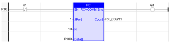
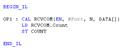
(* RCVCOM is a declared instance of RCVCOMM function block *)
RCVCOM (EN, #Port, N, DATA[]);
COUNT := RCVCOM.COUNT;
FBD Language
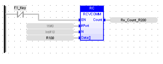
LD Language
IL Language
(* RCVCOM is a declared instance of RCVCOMM function block *)
Return to the Top: Serial Operations for IEC
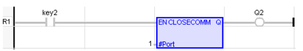
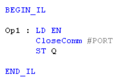
Close Communications Port
Operator - Performs the closure of the channel of the selected port.
Inputs
EN : Enable input (TYPE : BOOL![]() Boolean- [Data Type BOOL] - A single bit, binary value, or register/variable. Boolean points have only two possible values, 'TRUE' or 'FALSE'.)
Boolean- [Data Type BOOL] - A single bit, binary value, or register/variable. Boolean points have only two possible values, 'TRUE' or 'FALSE'.)
#PORT: Port number (TYPE : DINT![]() Double Integer - [Data Type DINT] - A 32-bit signed value. Double Integers are used where the value of the data is expected to be in the range of -2,147,483,648 to +2,147,483,647.)
Double Integer - [Data Type DINT] - A 32-bit signed value. Double Integers are used where the value of the data is expected to be in the range of -2,147,483,648 to +2,147,483,647.)
Outputs
Q : Output if the port closure is successful / Port already closed. (TYPE : BOOL) - If you attempt to close a port that does not exist, power flow through the element is FALSE.
Remarks
This element closes the channel to the selected port. There are no operational parameters except the Port Number. This entry must be a decimal constant.
ST Language
Q := CloseComm (EN, #Port) ;
FBD Language

LD Language
IL Language
Return to the Top: Serial Operations for IEC
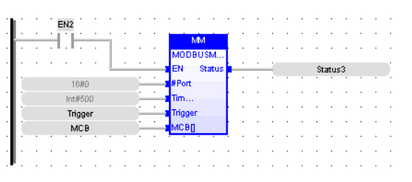
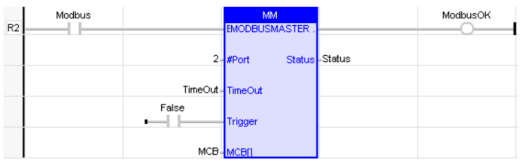
Modbus Master 
Operator – Configures a opened port as Modbus master.
Inputs
EN : Enable input (TYPE : BOOL)
#Port: (TYPE : DINT) - The communication port previously open by the ladder program with Protocol set to Modbus ASCII or Modbus RTU.
Timeout: (TYPE : INT) - Specified as either a register reference, or as a decimal constant (with a range of 0 to 1023). This specifies the amount of time that is allowed between a Modbus command and its response. This parameter is in terms of 100 milliseconds (i.e., 100 = 10.0 Sec).
Trigger: (TYPE : BOOL) - Specified as a bit register reference. When this bit goes from an off to on transition, the block transmits the Modbus message defined by the message control block ( MCB). When this input is low, the status word is cleared.
MCB[ ]: Message Control Box (TYPE : INT[]) - Specified as a register reference. This register is the first of six (6) registers that contain the control information for this block.
Outputs
Status: (TYPE : INT) - A WORD (16-bit) register used to hold the results of the element.
Remarks
MCB: Message Control Box
-
Word 1 Slave ID - value from 1 to 247 indicating the device to receive the message
-
Word 2 Modbus Command - Modbus command to send to the slave
-
Word 3 Slave Offset - Starting point in the Modbus slave for data to read or write - 1
-
Word 4 Data Length - Amount of data to read or write
-
Word 5 Controller Reference Type - Enumerated controller register type
-
Word 6 Controller Reference Offset - Controller register number - 1
Status bit assignment:
| Bit Number | Status |
|---|---|
| 1 | Request Succeeded (OK) |
| 2 |
Request Failed (See additional errors below) |
| 3 | ID out of range |
| 4 | Length exceeds Modbus frame |
| 5 | Command not supported |
| 6 | Invalid controller reference |
| 7 | Reserved |
| 8 | Reserved |
| 9 | Timeout Expired |
| 10 | Frame or parity error |
| 11 | Invalid checksum / crc from slave |
| 12 | Invalid format from slave |
| 13 | Slave rejected the command |
| 14 | Slave rejected the address |
| 15 | Slave rejected the data |
| 16 | Slave device error |
This function passes power flow if the associated port is opened and ready for communications.
ST Language
(* ModMaster is a declared instance of ModbusMaster function block *)
ModMaster (EN, #Port, Timeout, Trigger, MCB[]);
status:=ModMaster.Status
FBD Language
LD Language
IL Language
(* ModMaster is a declared instance of ModbusMaster function block *)
Return to the Top: Serial Operations for IEC
Modbus Slave 
Operator – Configures a opened port as Modbus Slave.
Inputs
EN: Enable input (TYPE : BOOL)
#Port: (TYPE : DINT) - The communication port previously open by the ladder program with Protocol set to Modbus ASCII or Modbus RTU.
Address: (TYPE : INT) - This specifies either a register or as a decimal constant (with a range of 1 to 247). This specifies the Modbus address the controller uses to respond to Modbus request
Time: (TYPE : INT) - This specifies either a register or as a decimal constant (with a range of 0 to 1023). This specifies the amount of time that may pass between request from the master before the in-activity timeout bit is set in the status word. This parameter is in terms of 100 milliseconds (i.e., 100 = 10.0 Sec).
Outputs
Status: (TYPE : INT) - A WORD (16-bit) register used to hold the results of the element.
Remarks
Status bit assignments:
| Bit Number | Status |
|---|---|
| 1 | Inactivity Timeout |
| 4 | Valid message received (toggles) |
| 5 | Parity error (single pass) |
| 6 | Frame Error (single pass) |
| 7 | Overrun error (single pass) |
| 8 | Crc/Checksum error (single pass) |
ST Language
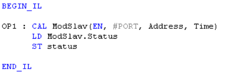
(* ModSlav is a declared instance of ModSlave function block *)
ModSlav (EN, #PORT, Address, Time):
Status:= ModSlav.Status;
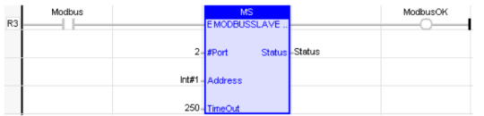
FBD Language
LD Language
IL Language
(* ModSlav is a declared instance of ModSlave function block *)
Return to the Top: Serial Operations for IEC
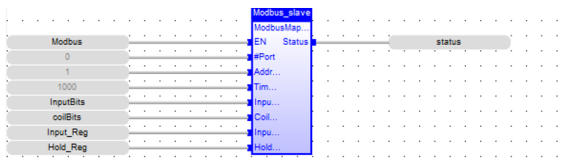
Modbus Map Slave
Also called: MODBUSMAPSLAVE. See also: Enhanced IEC 61131 Guide
NOTE: This feature requires Enhanced IEC License.
Operator – Configures a opened port as Modbus Slave.
Inputs
EN: Enable input (TYPE : BOOL)
#Port: (TYPE : DINT) - The communication port previously open by the ladder program with Protocol set to Modbus ASCII or Modbus RTU.
Address: (TYPE : INT) - This specifies either a register or as a decimal constant (with a range of 1 to 247). This specifies the Modbus address the controller uses to respond to Modbus request
Time: (TYPE : INT) - This specifies either a register or as a decimal constant (with a range of 0 to 1023). This specifies the amount of time that may pass between request from the master before the in-activity timeout bit is set in the status word. This parameter is in terms of 100 milliseconds (i.e., 100 = 10.0 Sec).
Input_Bits[]: (Type: Bool) - Specified as an array of Bool variable that is considered as Input Bits to be read by Master controller.
Coil_Bits[]: (Type: Bool) - Specified as an array of Bool variable that is considered as Coil Bits to be read/write by Master controller.
Input_Register[]: (Type: Int) - Specified as an array of Int variable that is considered as Input Registers to be read by Master controller.
Holding_Register[]: (Type: Int) - Specified as an array of Int variable that is considered as Holding Registers to be read/write by Master controller.
Outputs
Status: (TYPE : INT) - A WORD (16-bit) register used to hold the results of the element.
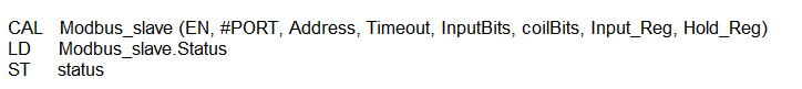
ST Language
(* Modbus_slave is a declared instance of ModbusMapSlave function block *)
Modbus_slave ( EN, #PORT, Address, Timeout, InputBits, coilBits, Input_Reg, Hold_Reg );
status := Modbus_slave.Status;
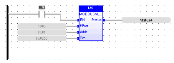
FBD Language
LD Language
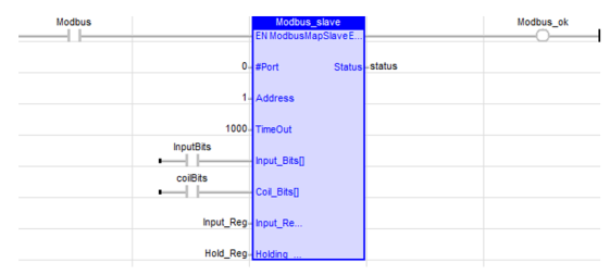
IL Language
(* Modbus_slave is a declared instance of ModbusMapSlave function block *)
Return to the Top: Serial Operations for IEC
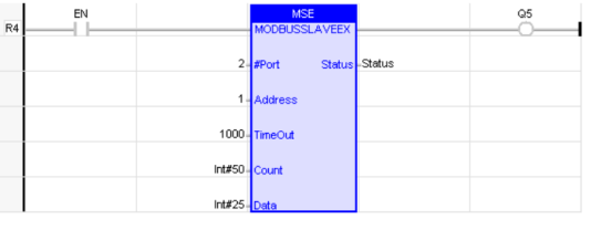
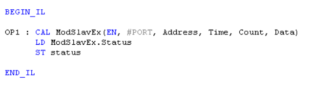
Modbus Slave Exception
Operator – Configures a opened port as Modbus Slave with Exception Message.
Inputs
EN: Enable input (TYPE : BOOL)
#Port: (TYPE : DINT) - The communication port previously open by the ladder program with Protocol set to Modbus ASCII or Modbus RTU.
Address: (TYPE : INT) - This specifies either a register or as a decimal constant (with a range of 1 to 247). This specifies the Modbus address the controller uses to respond to Modbus request.
Time: (TYPE : INT) - This specifies either a register or as a decimal constant (with a range of 0 to 1023). This specifies the amount of time that may pass between request from the master before the in-activity timeout bit is set in the status word. This parameter is in terms of 100 milliseconds (i.e., 100 = 10.0 Sec).
COUNT: (TYPE : INT) - This specifies as a register. This contains the number of bytes in the Message Data buffer to send. Transition from zero to a non-zero value triggers the transmission of one Exception Message.
DATA: (TYPE : INT) - This specifies as a register. This is the first register number of an array, which contains the Exception Message.
Outputs
Status: (TYPE : INT) - A WORD (16-bit) register used to hold the results of the element.
Remarks
Status bit assignments:
| Bit Number | Status |
|---|---|
| 1 | Inactivity Timeout |
| 4 | Valid message received (toggles) |
| 5 | Parity error (single pass) |
| 6 | Frame Error (single pass) |
| 7 | Overrun error (single pass) |
| 8 | Crc/Checksum error (single pass) |
| 9 | Exception message send (reset when e_cnt = 0) |
| 10 | Exception message exceeds send buffer size (reset when e_cnt = 0) |
| 11 | Attempt to send exception message when transmit busy (reset when e_cnt = 0) |
ST Language
(* ModSlavEx is a declared instance of ModSlaveEx function block *)
ModSlavEx (EN, #PORT, Address, Time, Count, Data);
Status:= ModSlavEx.Status;
FBD Language
LD Language
IL Language
Return to the Top: Serial Operations for IEC
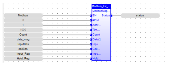
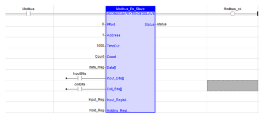
Modbus Map Extended Slave
See also: Enhanced IEC 61131 Guide
Operator – Configures a opened port as Modbus Slave with Exception Message.
Inputs
EN: Enable input (TYPE : BOOL)
#Port: (TYPE : DINT) - The communication port previously open by the ladder program with Protocol set to Modbus ASCII or Modbus RTU.
Address: (TYPE : INT) - This specifies either a register or as a decimal constant (with a range of 1 to 247). This specifies the Modbus address the controller uses to respond to Modbus request.
Time: (TYPE : INT) - This specifies either a register or as a decimal constant (with a range of 0 to 1023). This specifies the amount of time that may pass between request from the master before the in-activity timeout bit is set in the status word. This parameter is in terms of 100 milliseconds (i.e., 100 = 10.0 Sec).
COUNT: (TYPE : INT) - This specifies as a register. This contains the number of bytes in the Message Data buffer to send. Transition from zero to a non-zero value triggers the transmission of one Exception Message.
DATA: (TYPE : INT) - This specifies as a register. This is the first register number of an array, which contains the Exception Message.
Input_Bits[]: (Type: Bool) - Specified as an array of Bool variable that is considered as Input Bits to be read by Master controller.
Coil_Bits[]: (Type: Bool) - Specified as an array of Bool variable that is considered as Coil Bits to be read/write by Master controller.
Input_Register[]: (Type: Int) - Specified as an array of Int variable that is considered as Input Registers to be read by Master controller.
Holding_Register[]: (Type: Int) - Specified as an array of Int variable that is considered as Holding Registers to be read/write by Master controller.
Outputs
Status: (TYPE : INT) - A WORD (16-bit) register used to hold the results of the element.
Remarks
Status Bit Assignments:
|
Bit Number |
Status |
|
1 |
Inactivity Timeout |
|
4 |
Valid message received (toggles) |
|
5 |
Parity error (single pass) |
|
6 |
Frame Error (single pass) |
|
7 |
Overrun error (single pass) |
|
8 |
Crc/Checksum error (single pass) |
| 9 | Exception message send (reset when e_cnt = 0) |
| 10 | Exception message exceeds send buffer size (reset when e_cnt = 0) |
| 11 | Attempt to send exception message when transmit busy (reset when e_cnt = 0) |
ST Language
(* Modbus_Ex_slave is a declared instance of ModbusMapExtendedSlave function block *)
Modbus_Ex_Slave ( EN, #PORT, Address, Timeout, Count, data_msg, InputBits, coilBits, Input_Reg, Hold_Reg );
status := Modbus_Ex_Slave.Status;
FBD Language
LD Language
IL Language
(* Modbus_Ex_slave is a declared instance of ModbusMapExtendedSlave function block *)

Return to the Top: Serial Operations for IEC
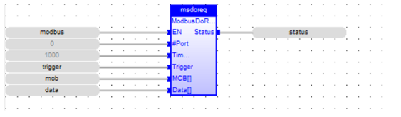
Modbus Do Request
See also: Enhanced IEC 61131 Guide
Operator – Configures a opened port as Modbus master.
Inputs
EN : Enable input (TYPE : BOOL)
#Port: (TYPE : DINT) - The communication port previously open by the ladder program with Protocol set to Modbus ASCII![]() ASCII - American Standard Code for Information Interchange - ASCII-coded characters are single-byte values in the range of 0 (zero) to 127. Codes in the range 128 to 255 are not defined by the ASCII standard, but rather by the equipment manufacturer. or Modbus RTU
ASCII - American Standard Code for Information Interchange - ASCII-coded characters are single-byte values in the range of 0 (zero) to 127. Codes in the range 128 to 255 are not defined by the ASCII standard, but rather by the equipment manufacturer. or Modbus RTU![]() RTU - Remote Terminal Unit - A microprocessor-based device that monitors and controls field devices, that then connects to plant control or SCADA (supervisory control and data acquisition) systems..
RTU - Remote Terminal Unit - A microprocessor-based device that monitors and controls field devices, that then connects to plant control or SCADA (supervisory control and data acquisition) systems..
Timeout: (TYPE : INT) - Specified as either a register reference, or as a decimal constant (with a range of 0 to 1023). This specifies the amount of time that is allowed between a Modbus command and its response. This parameter is in terms of 100 milliseconds (i.e., 100 = 10.0 Sec).
Trigger: (TYPE : BOOL) - Specified as a bit register reference. When this bit goes from an off to on transition, the block transmits the Modbus message defined by the message control block ( MCB). When this input is low, the status word is cleared.
MCB[ ]: Message Control Box (TYPE : INT[]) - Specified as a register reference. This register is the first of six (6) registers that contain the control information for this block.
Data[ ]: (Type :Any) - Specified as either an array of Bool or array of words variable. User must configure this Input based on the MODBUS command type.
Outputs
Status: (TYPE : INT) - A WORD (16-bit) register used to hold the results of the element.
ST Language
(* ModMaster is a declared instance of ModbusDoRequest function block *)
ModMaster(En, #PORT, Timeout, Trigger, MCB[], Data[]);
status:= ModMaster.Status;
FBD Language
LD Language
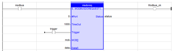
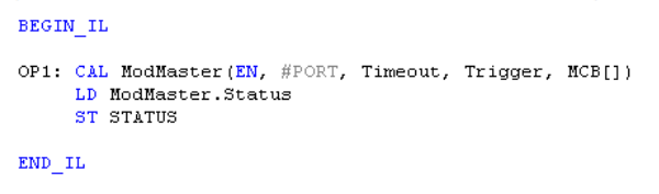
IL Language
(* ModMaster is a declared instance of ModbusDoRequest function block *)
CAL ModMaster(En, #PORT, Timeout, Trigger, MCB[], Data[])
LD ModMaster.Status
ST status
Return to the Top: Serial Operations for IEC
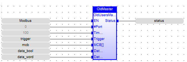
Old User Master
Also called: OLDUSERMASTER. See also: Enhanced IEC 61131 Guide
Operator – Configures an opened port as Modbus master.
Inputs
EN : Enable input (TYPE : BOOL)
#Port: (TYPE : DINT) - The communication port previously open by the ladder program with Protocol set to Modbus ASCII or Modbus RTU.
Timeout: (TYPE : INT) - Specified as either a register reference, or as a decimal constant (with a range of 0 to 1023). This specifies the amount of time that is allowed between a Modbus command and its response. This parameter is in terms of 100 milliseconds (i.e., 100 = 10.0 Sec).
Trigger: (TYPE : BOOL) - Specified as a bit register reference. When this bit goes from an off to on transition, the block transmits the Modbus message defined by the message control block ( MCB). When this input is low, the status word is cleared.
MCB[ ]: Message Control Box (TYPE : INT[]) - Specified as a register reference. This register is the first of six (6) registers that contain the control information for this block.
Data_bool[ ]: (Type :Bool) - Specified as an array of Bool variable that user needs to Read or Write.
Data_Word[ ]: (Type :Int) - Specified as an array of Int variable that user needs to Read or Write.
Outputs
Status: (TYPE : INT) - A WORD (16-bit) register used to hold the results of the element.
Remarks
1. MCB: Message Control Box
-
Word 1 Slave ID - value from 1 to 247 indicating the device to receive the message
-
Word 2 Modbus Command - Modbus command to send to the slave
-
Word 3 Slave Offset - Starting point in the Modbus slave for data to read or write - 1
-
Word 4 Data Length - Amount of data to read or write
-
Word 5 Controller Reference Type - Enumerated controller register type
-
Word 6 Controller Reference Offset - Controller register number - 1
2. Status Bit Assignment
|
Bit Number |
Status |
|
1 |
Request Succeeded (OK) |
|
2 |
Request Failed (See additional errors below) |
|
3 |
ID out of range |
|
4 |
Length exceeds Modbus frame |
|
5 |
Command not supported |
|
6 |
Invalid controller reference |
|
7 |
Reserved |
|
8 |
Reserved |
|
9 |
Timeout Expired |
|
10 |
Frame or parity error |
|
11 |
Invalid checksum / crc from slave |
|
12 |
Invalid format from slave |
|
13 |
Slave rejected the command |
|
14 |
Slave rejected the address |
|
15 |
Slave rejected the data |
|
16 |
Slave device error |
This function passes power flow if the associated port is opened and ready for communications.
ST Language
(* OldMaster is a declared instance of OldUserMaster function block *)
OldMaster ( EN, #PORT, Timeout, trigger, mcb, data_bool, data_word);
status := OldMaster.Status;
FBD Language
LD Language
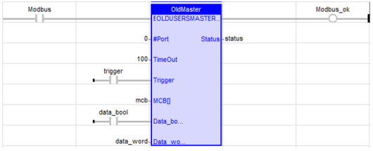
IL Language
(* OldMaster is a declared instance of OldUserMaster function block *)
CAL OldMaster (EN, #PORT, Timeour, trigger, mcb, data_bool, data_word)
LD OldMaster.Status
ST status
Return to the Top: Serial Operations for IEC
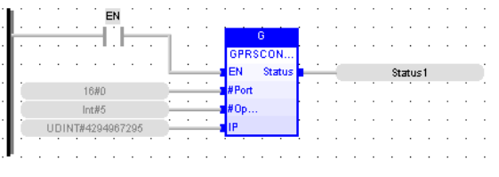
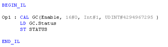
GPRS Connect
Operator – This block is used to establish communication between OCS and any other communicating devices having unique IP address and port configuration.
Inputs
EN : Enable input (TYPE : BOOL![]() Boolean- [Data Type BOOL] - A single bit, binary value, or register/variable. Boolean points have only two possible values, 'TRUE' or 'FALSE'.)
Boolean- [Data Type BOOL] - A single bit, binary value, or register/variable. Boolean points have only two possible values, 'TRUE' or 'FALSE'.)
#Port: (TYPE : DINT![]() Double Integer - [Data Type DINT] - A 32-bit signed value. Double Integers are used where the value of the data is expected to be in the range of -2,147,483,648 to +2,147,483,647.) - The communication port previously open by the ladder program.
Double Integer - [Data Type DINT] - A 32-bit signed value. Double Integers are used where the value of the data is expected to be in the range of -2,147,483,648 to +2,147,483,647.) - The communication port previously open by the ladder program.
#Option: (TYPE : INT![]() Integer - [Data Type INT] - A 16-bit signed value. Integers are used where the value of the data is expected to be in the range of -32,768 to +32,767.) - Type of protocol to be used.
Integer - [Data Type INT] - A 16-bit signed value. Integers are used where the value of the data is expected to be in the range of -32,768 to +32,767.) - Type of protocol to be used.
#IP: (TYPE : UDINT![]() Unsigned Double Integer - [Data Type UDINT] - A 32-bit unsigned value. Unsigned Double Integers are used where the value of the data is expected to be in the range of 0 (zero) to 4,294,967,296.) - IP address and Port number needs to be entered.
Unsigned Double Integer - [Data Type UDINT] - A 32-bit unsigned value. Unsigned Double Integers are used where the value of the data is expected to be in the range of 0 (zero) to 4,294,967,296.) - IP address and Port number needs to be entered.
Output
Status: (TYPE : INT) - A WORD![]() Word - [Data Type WORD] - A string of 16 consecutive bits. WORD values are used where the value of the data is not as important as the bit patterns (shifts and rotates). (16-bit) register used to hold the results of the element.
Word - [Data Type WORD] - A string of 16 consecutive bits. WORD values are used where the value of the data is not as important as the bit patterns (shifts and rotates). (16-bit) register used to hold the results of the element.
Remarks
1. #Ports : Ports selection (Values 0 - 1)
-
Port 1 (MJ1) = 0
-
Port 2 (MJ2) = 1
-
Port 3 (CN1 / COM) = 2
2. #Option : Protocol selection (Values 0 - 1)
3. #IP : IP address and Port number
Two types of modes are possible here, client and server mode.
-
Client Mode: In this mode OCS behaves as client and connects to specified server (Server IP/Port address to be specified as input).
-
Server Mode: In this mode OCS behaves as server and accepts connection requests from specified client. Client IP address to be specified as input. Note: Server mode of operation is supported only in case of SIM with static IP address
IP Address and Port number needs to be entered for ‘#IP (IP / Port Address)’. A register reference can also be provided here. If register reference is used, the IP and port details need to be provided at the mentioned register location.
There is support for IP and Port address entry in Binary format and automatic detection of Client or server mode based upon IP/Port address entry has been added.
-
For entry in binary format, data should start with string “IPBN” followed by IP and Port address in binary format.
-
For entry in string format, data should end with a null termination
Null Termination - To place a NULL character (character code 0) at the end of ASCII data. Some functions require NULL Termination to be able to determine the end point of the ASCII data since that data may vary in length from one time to the next. or space.
For automatic switching between client and server mode, if the port number is mentioned as 0, server mode connection would be made else client mode connection would be made. For example: If register reference %R100 is entered for IP/Port address.
Contents of %R100 in String Format:
Client Mode: %R100 = “10.111.64.2/10001” (Register %R100 to %R108 are used)
Server Mode: %R100 = “192.168.5.2” (Register %R100 to %R105 are used)
Contents of %R100 in Binary Format:
Client Mode:
-
%R100 = “IPBN”
-
%R102 = 10.111.64.2 (IP address in Binary Format)
-
%R104 = 10001 (Port address in Binary Format)
-
(Register R100 to R104 are used)
Server Mode:
-
%R100 = “IPBN”
-
%R102 = 192.168.5.2 (IP address in Binary Format)
-
%R104 = 0 (Zero, to indicate no Port Address)
-
(Register R100 to R104 are used)
4. Status bit assignment:
| Modem Status | Register Value | Modem Output Power |
|---|---|---|
| Modem is inactive | 65535 (0xFFFF) | Disabled |
| Modem command started and waiting for response | 65534 (0xFFFE) | Disabled |
| Modem is not responding (Command Timeout) |
65533 (0xFFFD) |
Disabled |
|
Modem Command succeeded |
0 (0x0) |
Enabled (Only in case of Initialization modem command else Disabled) |
|
Modem is connected to destination server |
1 (0x1) |
Enabled |
| Modem is Ringing (i.e. incoming call) | 2 (0x2) | Disabled |
| Modem detected no/lost carrier | 3 (0x3) | Disabled |
| Modem command syntax error | 4 (0x4) | Disabled |
|
SMS functionality is Active |
5 (0x5) |
Disabled |
|
Modem in Listen (Server) Mode |
6 (0x6) |
Disabled |
ST Language
GC (Enable, 16#0, Int#1, UDINT#45 );
STATUS:= GC.Status;
FBD Language
LD Language
![]()
IL Language
Return to the Top: Serial Operations for IEC
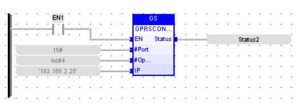
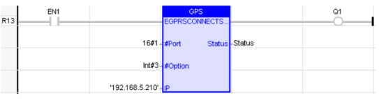
GPRS ConnectS
Operator – This block is used to establish communication between OCS and any other communicating devices having unique IP address and port configuration.
Inputs
EN : Enable input (TYPE : BOOL)
#Port: (TYPE : DINT) - The communication port previously open by the ladder program.
#Option: (TYPE : INT) - Type of protocol to be used.
#IP: (TYPE : String) - IP address to be entered.
Output
Status: (TYPE : INT) - A WORD (16-bit) register used to hold the results of the element.
Remarks
1. #Ports : Ports selection (Values 0 - 1)
-
Port 1 (MJ1) = 0
-
Port 2 (MJ2) = 1
-
Port 3 (CN1 / COM) = 2
2. #Option : Protocol selection (Values 0 - 1)
3. #IP : IP address
Two types of modes are possible here, client and server mode.
-
Client Mode: In this mode OCS behaves as client and connects to specified server (Server IP/Port address to be specified as input).
-
Server Mode: In this mode OCS behaves as server and accepts connection requests from specified client. Client IP address to be specified as input. NOTE: Server mode of operation is supported only in case of SIM with static IP address.
IP Address and Port number needs to be entered for ‘#IP (IP / Port Address). There is support for IP and Port address entry in Binary format and automatic detection of Client or server mode based upon IP/Port address entry has been added.
-
For entry in binary format, data should start with string “IPBN” followed by IP and Port address in binary format.
-
For entry in string format, data should end with a null termination
Null Termination - To place a NULL character (character code 0) at the end of ASCII data. Some functions require NULL Termination to be able to determine the end point of the ASCII data since that data may vary in length from one time to the next. or space. -
For automatic switching between client and server mode, if the port number is mentioned as 0, server mode connection would be made else client mode connection would be made.
Examples:
In String Format:
-
Client Mode: '10.111.64.2/10001'
-
Server Mode: '192.168.5.2'
In Binary Format:
Client Mode:
'IPBN/10.111.64.2/10001'
Server Mode:
'IPBN/192.168.5.2/0'
Here 0 (Zero) indicates no port.
4. Status bit assignment:
| Modem Status | Register Value | Modem Output Power |
|---|---|---|
| Modem is inactive | 65535 (0xFFFF) | Disabled |
| Modem command started and waiting for response | 65534 (0xFFFE) | Disabled |
| Modem is not responding (Command Timeout) |
65533 (0xFFFD) |
Disabled |
|
Modem Command succeeded |
0 (0x0) |
Enabled (Only in case of Initialization modem command else Disabled) |
|
Modem is connected to destination server |
1 (0x1) |
Enabled |
| Modem is Ringing (i.e. incoming call) | 2 (0x2) | Disabled |
| Modem detected no/lost carrier | 3 (0x3) | Disabled |
| Modem command syntax error | 4 (0x4) | Disabled |
|
SMS functionality is Active |
5 (0x5) |
Disabled |
|
Modem in Listen (Server) Mode |
6 (0x6) |
Disabled |
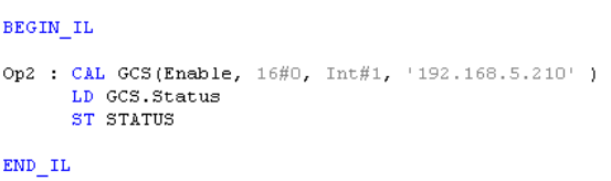
ST Language
GCS(Enable, 16#0, Int#1, '192.168.5.210' ) ;
Status:= GCS.Status;
FBD Language
LD Language
IL Language
Return to the Top: Serial Operations for IEC
Modem Auto Answer
Operator – Places the specified modem in Auto-answer mode. The modem will answer incoming calls after the specified number of rings. Set the number of rings to zero to disable auto answer mode on the modem.
Inputs
EN : Enable input (TYPE : BOOL)
#Port: (TYPE : DINT) - The communication port opened.
# NbRing: (TYPE : DINT) - Number of Rings, after which the modem answers the call.
Outputs
Status: (TYPE : INT) - Status indicates the progress and success or failure of the operations.
Remarks
1) General Status Results - The modem function block returns a status word to indicate the progress and success or failure of the operations. All Actions share this result information:
| Status | Description |
|---|---|
|
-1
|
When the function is not active, output from the function block is OFF. |
| -2 | When the function is being executed, the output remains OFF. |
| -3 |
When a function times-out, because the modem did not respond, the output remains OFF. |
| 0 |
The modem accepted the command, the output depends on the function. |
-
The modem successfully connected, the output turns ON.
-
When an incoming ring is detected, the output remains OFF.
-
The modem loses carrier, the output turns OFF.
-
When the command results in an error, the output remains OFF.
2) Action - When the input to this function block transitions from OFF to ON, the controller attempts to set the modem to auto answer mode. When the modem has been placed in auto answer mode, the function block output remains OFF, and the status is loaded with 0 to indicate the modem is OK. Power flow into the function block must be kept ON at this point. When an incoming call is received,the output of the function block remains OFF, and the status is loaded with 2 to indicate ringing. After the programmed number of rings, the modem answers. If a connection is established, the output of the function block turns ON and the status is loaded with 1 to indicate a connection. If the connection is lost, (other side hangs-up ...) the output turns OFF and the status is loaded with 3 to indicate a loss of carrier. If the modem is connected to another device and the input to the function block transitions from ON to OFF, the modem hangs-up, the function block output turns OFF, and the status is loaded with -1 to show the function block is inactive.
ST Language
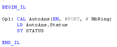
(* AutoAns is a declared instance of ModemAutoAnswer function block *)
AutoAns (EN, #PORT, #NbRing);
Status:= AutoAns.Status;
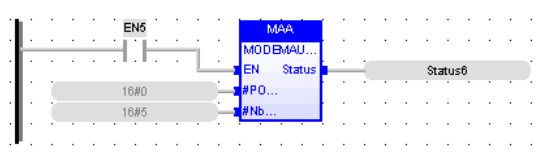
FBD Language
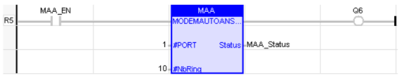
LD Language
IL Language
(* AutoAns is a declared instance of ModemAutoAnswer function block *)
Return to the Top: Serial Operations for IEC
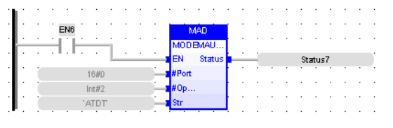
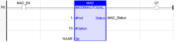
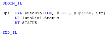
Modem Auto Dial
Operator – Perform dialing to a modem with the supplied phone number.
Inputs
EN : Enable input (TYPE : BOOL)
#Port: (TYPE : DINT) - The communication port opened.
#Option: (TYPE : INT) - Option is the command your modem requires to initiate dialing.
Str: (TYPE : STRING) - Str is the number to be dialed. Do not use spaces, dashes, or any other punctuations except those required by the modem.
Outputs
Status: (TYPE : INT) - Status indicates the progress and success or failure of the operations.
Remarks
1) Action - When the input to this function block transitions from OFF to ON, the controller attempts to dial the modem with the supplied phone number. If the modem dials and successfully connects to another modem, the output of the function block turns ON, and status is loaded with 1 to indicate a connection. Keeping power flow to the dial function block allows the controller to monitor the connection. If the connection is lost (the other side hangs-up...), the output to the function block turns OFF and the status is loaded with 3 to indicate a loss of carrier. If the input to this function block transitions from ON to OFF, the modem hangs up, the function block output turns OFF, and the status is loaded with -1 to show the function block is inactive.
2) Number to be Dialed - Specifies the phone number to be dialed. Dependent on the modem used it is also possible to include special commands in the dial string, such as those necessary to insert a pause or to defeat Call Waiting. Typically a comma "," may be used to insert a pause, for example when it is required to obtain an outside line.
Examples:
-
9,7654321 Dials for an outside line, pauses to make the connection, then dials local number 765-4321
-
*7013175551212 Disables Call Waiting, then dials long distance to (317)555-1212.
3) Option - The above command is modem specific. The values default to common commands used to program modems using the industry standard AT command set. Most current modems implement this command structure, but refer to the User Manual that comes with the modem in order to determine the exact strings necessary to perform these tasks.
ST Language
(* AutoDial is a declared instance of ModemAutoDial function block *)
AutoDial (EN, #PORT, #Option, Str);
Status := AutoDial.Status;
FBD Language
LD Language
IL Language
(* AutoDial is a declared instance of ModemAutoDial function block *)
Return to the Top: Serial Operations for IEC
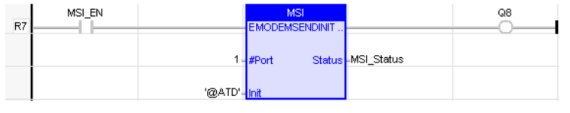
Modem Send Init String
Operator – Perform checking of Modem by sending the initialization string
Inputs
EN : Enable input (TYPE : BOOL)
#PORT: (TYPE : DINT) - The communication port opened.
INIT: (TYPE : STRING) - Initialization String.
Outputs
Status: (TYPE : INT) -Status indicates the progress and success or failure of the operations.
Remarks
1) Action - When the input to this function block transitions from OFF to ON, the controller sends the initialization string to the modem. If the modem returns an OK response, the output of the function block turns ON, and the status register is loaded with 0. If the modem returns an error response because the init string is not valid, the status register is loaded with a 4. If the modem does not respond, the status is loaded with -3 indicating a timeout.
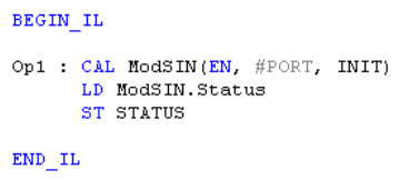
ST Language
(* ModSIN is a declared instance of ModSendInit function block *)
ModSIN (EN, #PORT, INIT);
Status := ModSIN.Status
FBD Language
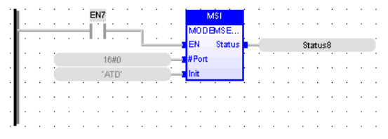
LD Language
IL Language
(* ModSIN is a declared instance of ModSendInit function block *)
Return to the Top: Serial Operations for IEC
Operands for Communication Ports
The following values can be fed to different Parameters of the block:
1. #Ports : Ports selection (Values 0 - 3)
| Port 1 (MJ1) = 0 |
| Port 2 (MJ2) = 1 |
| Port 3 (CN1/COM) = 2 |
| MJ3 Port = 3 |
2. #Baud : The Baud should be the same as that of the other device it is communicating to.
| BAUD_300 |
// 0 = 300 baud |
| BAUD_600 |
// 1 = 600 baud |
| BAUD_1200 |
// 2 = 1200 baud |
| BAUD_2400 |
// 3 = 2400 baud |
| BAUD_4800 |
// 4 = 4800 baud |
| BAUD_9600 |
// 5 = 9600 baud |
| BAUD_19200 |
// 6 = 19200 baud |
| BAUD_38400 |
// 7 = 38400 baud |
| BAUD_57600 |
// 8 = 57600 baud |
| BAUD_115200 |
// 9 = 115200 baud |
| BAUD_14400 |
// 10 = 14400 baud |
| BAUD_28800 |
// 11 = 28800 baud |
| BAUD_10400 |
// 12 = 10400 baud |
3. #Parity : Parity can be configured as 0- 4
| PARITY_NONE |
0 = No parity |
| PARITY_ODD |
1 = Odd parity |
| PARITY_EVEN |
2 = Even parity |
| PARITY_MARK |
3 = Mark parity |
| PARITY_SPACE |
4 = Space parity |
4. #Data : Data bit can be 5 to 8
| DATA BITS |
0 = 5 data bits |
| DATA BITS |
1 = 6 data bits |
| DATA BITS |
2 = 7 data bits |
| DATA BITS |
3 = 8 data bits |
5. #Stop : Stop bits can be configured as 1 or 2
| STOP_1 |
// 0 = 1 stop bit |
| STOP_2 |
// 1 = 2 stop bits |
6. #Handshake : Handshake can be configured as 0 to 5
| HANDSHAKE_NO |
// 0 = No Handshaking |
| HANDSHAKE_SW |
// 1 = Software handshaking ( XON/ XOFF) |
| HANDSHAKE_HW |
// 2 = Hardware handshaking ( RTS/ CTS) |
| HANDSHAKE_MD_FD |
// 3 = Multidrop full-duplex handshaking |
| HANDSHAKE_MD_HD |
// 4 = Multidrop half-duplex handshaking |
| HANDSHAKE_RM |
// 5 = Radio modem handshaking |
7. #Protocol : Protocol can be configured as 0 to 5
| PROTOCOL_RISM |
// 0 = RISM protocol |
| PROTOCOL_CsCAN |
// 1 = CsCAN protocol (not supported) |
| PROTOCOL_GENERIC |
// 2 = Generic ladder-driven protocol |
| PROTOCOL_RTU |
// 3 = Modbus RTU ladder-driven protocol |
| PROTOCOL_ASCII |
// 4 = Modbus ASCII ladder-driven protocol |
| PROTOCOL_MODBUS_TCP |
// 5 = Modbus TCP ladder - driven protocol |
8. #Mode : Mode can be configured as 0 to 2
| PORT_RS232 |
// 0 = Enable RS232 port |
| PORT_RS485 |
// 1 = Enable RS485 port PORT_OPTION1 |
| Modem |
// 2 = Modem;XLE |
| Ethernet |
// 3 = Ethernet |
| Fiber A |
// 4 = Fiber A |
| Fiber B |
// 5 = Fiber B |
| GSM Dual |
// 6 = GSM Dual |
| GSM Quad |
// 7 = GSM Quad |
| Radio 900MHZ |
// 8 = Radio 900Mhz |
| Radio Zigbee |
// 9 = Radio Zigbee |
NOTES:
-
Modbus RTU forces 8 data bits
-
Modbus ASCII forces 7 data bits
Return to the Top: Serial Operations for IEC